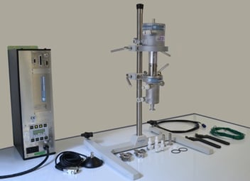
The BSP-1200 bench-scale ultrasonic liquid processor is a Barbell Horn Ultrasonic Technology (BHUT)-based system, designed for process optimization and medium-scale production. It can be implemented in two processing modes: flow-through and batch. When a large amount of material needs to be processed, the former is preferable because it results in a much higher processing capacity, improved ultrasonic exposure uniformity, and better temperature control.
When configured in the flow-through mode, the processor is supplied with four main components: a 1,200 W ultrasonic Generator, a water-cooled piezoelectric Transducer, a Barbell Horn, and a Reactor Chamber (flow cell). Although it is supplied mostly pre-assembled and ready-to-use, knowing how to put it together can be helpful. In this blog post, we provide step-by-step assembly instructions for the BSP-1200 configured in the flow-through mode.
Please keep in mind this blog post is relevant to BSP-1200 system units shipped before April, 2021.
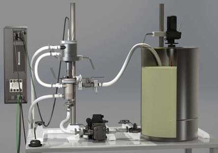
Please review the BSP-1200 User Manual and familiarize yourself with the processor. Fig. 1 identifies all major components of the fully assembled system.
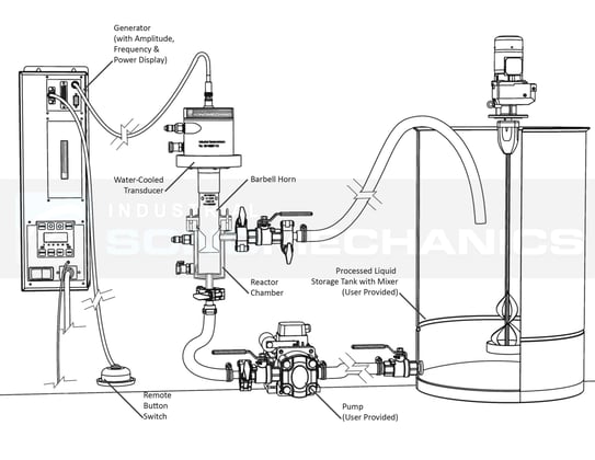 |
Figure 1. BSP-1200 ultrasonic processor assembled in the flow-through mode.
ASSEMBLY INSTRUCTIONS:
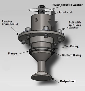
Figure 2. Parts involved in steps 1 - 4 of the assembly procedure.
1. Place the Top O-ring above the flange of the Barbell Horn.
2. Place the Reactor Chamber lid with six bolts (or wing screws) and split-lock washers above the Top O-ring.
3. Place the Mylar acoustic washer over the connecting stud.
4. Place the Bottom O-ring below the flange of the Barbell Horn.
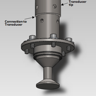
Figure 3. Step 5 of the assembly procedure.
5. Thread the Barbell Horn all the way into the Transducer by hand.
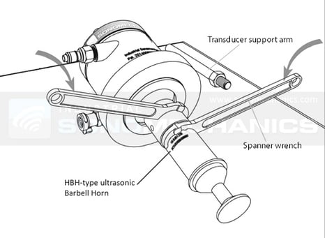 |
Figure 4. Step 6 of the assembly procedure.
6. Tighten the assembly using the provided Spanner Wrenches:
a) Insert the pin of the first Spanner Wrench into a hole in the Transducer’s front mass and set it up to provide counterclockwise torque.
b) Insert the pin of the second Spanner Wrench into a hole in the Barbell Horn’s input end and set it up to provide clockwise torque.
c) Tighten by firmly pressing down with your palms on the wrenches, using the weight of your body. Please note, that a power overload error during system operation may indicate an insufficiently tightened Transducer-Horn assembly.
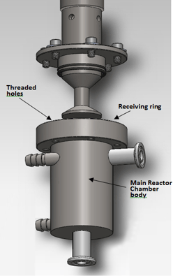 Figure 5. Steps 7 - 8 of the assembly procedure.
7. Lower the Reactor Chamber lid until it is in contact with the top O-ring.
8. Insert the Barbell Horn into the Reactor Chamber until the Bottom O-ring is in contact with the receiving ring of the Reactor Chamber.
9. Align the Transducer's and Reactor Chamber's Support Arm holes.
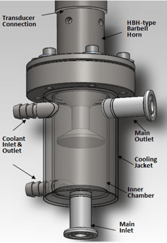
Figure 6. Steps 11 - 12 of the assembly procedure.
10. Align the lid such that the wing screws match up to the threaded holes in the receiving ring.
11. Thread the screws into the receiving ring of the Reactor Chamber. Tighten by hand using a crossing pattern in order to maintain the same tension on all sides.
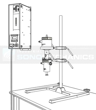 |
Figure 7. Steps 12 - 18 of the assembly procedure.
12. Thread the Support Arms into the Transducer and Reactor Chamber and tighten the counter-nuts. Make sure that the Support Arms are parallel to each other.
13. Secure the top clamp holder on the support stand rod.
14. Adjust the position and secure the bottom clamp holder such that both Support Arms can be accommodated.
15. Slide both Support Arms into the corresponding clamp holders.
16. Secure the Reactor Chamber's Support Arm in the bottom clamp holder.
17. Secure the Transducer's support arm in the top clamp holder.
18. Loosen and re-tighten the top clamp holder, removing any strain in the assembly.
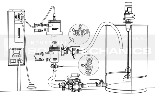 |
Figure 8. Steps 19 - 23 of the assembly procedure.
19. Assemble all hose/piping connections for the peripheral equipment.
20. Hang the Generator on a wall or place it in a rack.
21. Assemble the Reactor Chamber's inlet and outlet hose/piping connections.
22. During continuous operation, it is important to cool the Transducer with flowing cold water (5 - 10 L/min, 5 - 10 oC ). Attach the Transducer's cooling jacket to a cold water source.
23. Attach Reactor Chamber's cooling jacket to a cold water source (optional).
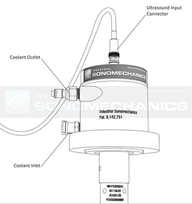 |
Figure 9. Step 24 of the assembly procedure.
24. Connect one end of the Ultrasound Cable to the Generator and the other end to the Transducer.
25. Connect the Remote Button Switch to the Generator.
26. Plug the Generator's power cable into a power outlet.
27. Make sure you use adequate ear protection while operating the system. For more information, see this blog post.
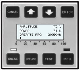
28. Before putting any liquid through the Reactor Chamber, activate the ultrasonic output and check the power on the Generator's display (see Power Test Instructions, below).
|
POWER TEST INSTRUCTIONS:
- Liquid present in the Reactor Chamber - Barbell Horn insufficiently tightened to the Transducer - Reactor Chamber lid tightened unevenly - Strain in the assembly
|
The BSP-1200 processor is now assembled and ready for continuous operation!
For further information, please download the BSP-1200 User Manual.
BSP-1200 instructional video: Barbell Horn replacement procedure.
.jpg?width=1994&height=332&name=Logo%20Sonomechanics%20White%20No%20Shadow%20R_Final%20(1).jpg)

